
Page 194 - Tungaloy Catalog
P. 194
T-CBN Series
Honing specifications
dT-CBN inserts with special honing specifications are made to order. Refer to the following description.
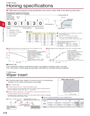
Designation system for honing
Example: Honing width W
Honing width .006 in
Honing angle - 30°
With R-honing Rake face
3 S 0 1 5 3 0 Honing angle α R-honing
Shape Honing width (W) Honing angle (α) Relief face
PCD and PCBN Tools S … Chamfered + R-honing n Symbol Amount of honing 20° Honing angle n Honing specification can be selected in combination
T … Chamfered honing
α
W
E … R-honing alone
of items described here.
005
10°
- 10°
.002 in
F … Sharp edges
n Inserts with “R” honing alone are available.
15°
- 15°
010
.004 in
Note: There are unavailable combinations.
013
- 20°
.005 in
For details, ask your nearest Tungaloy sales office.
015
.006 in
25°
020
- 30°
.008 in
30°
steels and other hard materials
35° - 25° Honing specifications for machining hardened
- 35°
Standard honing: .005" × 25° + R-honing
40° - 40° “-L” honing : .005" × 15° + R-honing
“-H” honing : .005" × 35° + R-honing
d Relationship between honing angle and tool life in continuous turning d Relationship between honing angle and tool life in interrupted turning
150 300
Cutting conditions Cutting conditions
Work material: Chromium molybdenum 200 Work material: Chromium molybdenum
steel (JIS SCM415), 60 HRC
Time in cut T (min) 100 Insert: TNGN 331 (BX360) Tool life (%) 100 Insert: TNGN 331 (BX360)
125
steel (JIS SCM415), 60 HRC
Cutting speed: Vc =330 SFM
Cutting speed: Vc = 330 SFM
Feed: f = .006 in/rev
Feed: f = .006 in/rev
Depth of cut: ap = .010 in
Depth of cut: a p = .010 in
75
Coolant: Dry
Tool life criterion: VBmax = .006 in Coolant: Dry
Tool life criterion: Fracture
50 Honing: 0.13 × hh°+ R-honing 0 Honing: 0.13 × hh° + R-honing
−15º −20º −25º −30º −35º −40º −15º −20º −25º −30º −35º −40º
Honing angle Honing angle
dGeneral rule
• For continuous cutting, small honing angle is favorable to minimize wear in general.
• For interrupted cutting, large honing angle is favorable to minimize fracture in general.
T-CBN Series
Wiper insert
Wiper edge geometry
d A finishing edge (wiper edge) is formed at the point of intersection
between corner radius and straight cutting edge.
j Effect of wiper edge
d Doubles the productivity g Reduced machining time
The wiper edge can double the feed rate and moreover does not deteriorate the
surface roughness. (Note: Feed rate: *f < .012 in/rev)
d Superior surface roughness g By integrating roughing and finishing into one
process, productivity can be increased.
Wiper edge
Compared with conventional inserts only with corner radius, surface roughness
can be improved with the wiper edge.
j Recommended toolholders for wiper-edged inserts
j Profiles of surface roughness Sectional profile of surface 2QP-CNGA 432 WL 3QP-WNGA 432 WL 2QP-DNGA 432 WJ 3QP-TNGA 431 WG
machined with conventional insert
Removed End cutting
angle 95˚ 93˚ 91˚
ACLNR/L*****12-A AWLNR/L*****08-A ADJNR/L*****15-A ATGNR/L*****16-A
External ATFNR/L*****16-A
Sectional profile of toolholder DTGNR/L*****16
surface machined with DCLNR/L*****12 DWLNR/L*****08 DDJNR/L*****15 DTFNR/L*****16
When machining wiper insert When machining Internal A***-ACLNR/L12-D*** A***-AWLNR/L08-D*** A***-ADUNR/L15-D*** A***-ATFNR/L16-D***
with conventional with wiper insert toolholder
insert
: Stocked items.
3–6 : Japan Stock