
Page 587 - Tungaloy Catalog
P. 587
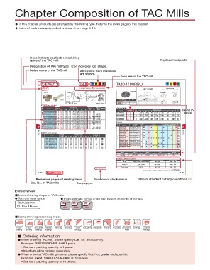
Chapter Composition of TAC Mills
u In this chapter, products are arranged by machining type. Refer to the index page of this chapter.
u Index of each standard product is shown from page 9-16.
Icons indicate applicable machining
types of the TAC mill. Replacement parts
Designation of TAC mill type Icon indicates tool shape.
Series name of the TAC mill Applicable work materials
are shown.
Features of the TAC mill
Screw-on type TAC Mills
T/EAW13 45° ~ .197in Air Hole Steel Stainless Cast Iron Non-ferrous TMD4400RBU Steel Stainless Cast Iron Non-ferrous
For general purpose milling of general steels, 45° LEAD Specifications
Face Chamfering stainless steels, cast irons, and non-ferrous metals 45° Lead Close Pitch Face Mill
Milling
ød Rake angle: A.R. 17° ~ 20° R.R. 16° ~ 11° Close Pitch
TAW13 Fig. A a Fig. B SD N42Z N SDKN42ZTNCR
b CM10×30H
CM12×30H
R
L f øDs
øD1 øDc TMBA-M16H
45° ap TMBA-M20H SDCN42ZFN-DIA Wiper WDCN42ZFR-DIA
EAW13 øDc 45° L f L R s Corner Angle 45°
Max. ap: øD1
Flat top = .196 in Mill body xing screw Rake Axial +15°
MJ, MS, AJ = .157 in
ML = .098 in HJ = .078 in Right hand (R) shown. Angle Radial -3°
TAW13 (Fig. A: bore type)
Pitch Cat. No. Stock No. of øDc øD1 ød Dimensions (in) Lf b a Weight hole Mill body Mounting TMD4400RBU Stock # of Dimensions (in) Wt. Items in
Air
fi xing
Inserts
(lbs)
details
R
screw
Cat. No.
d
D1
F
D
Coarse TAW13R200U0075A03 d 3 4 5 2.00 2.51 .750 1.378 1.575 0.20 0.32 0.9 With CM10×30H TMD4403RBU R d d L Teeth 3.150 3.780 1.000 1.024 1.969 .236 a .375 b lbs. stock
.750
E
3.00
3.51
With
2.0
0.24
1.969
1.00
1.02
0.38
6
TAW13R300U0100A04 d
3.1
4.52
4.00
0.63
0.32
3.8
TAW13R400U0150A05 d
1.969
1.50
With
CM12×30H
2.480
.394
8
.625
TMD4404RBU
3.937
1.260
1.500
5.5
4.528
With
TAW13R500U0150A06 d
2.00
TAW13R600U0200A07 d 6 7 5.00 5.51 1.50 1.457 2.480 0.39 0.63 6.2 Without TMBA-M16H TMD4405RBU d 10 4.921 5.472 1.500 1.260 2.480 .394 .625 7.9
0.39
TMBA-M20H
1.50
2.480
0.75
9.0
6.51
6.00
TAW13R200U0075A04 d 4 2.00 2.51 0.75 .750 1.575 0.20 0.32 0.9 With CM10×30H TMD4406RBU d d 14 18 6.299 6.811 2.000 1.496 2.480 .433 .750 12.1
7.874
8.370
18.9
TMD4408RBU
.551
1.000
2.480
1.496
2.500
1.02
Close TAW13R300U0100A06 d 6 7 3.00 3.51 1.00 1.378 1.969 0.24 0.38 2.0 With CM12×30H 9-148 TMD4410RBU d 22 9.842 10.335 2.500 1.496 2.480 .551 1.000 35.6
0.63
1.50
0.32
1.969
4.00
4.52
TAW13R400U0150A07 d
With
3.5
With
TAW13R500U0150A08 d
2.480
TMBA-M20H
2.00
6.00
TAW13R600U0200A10 d 8 10 5 5.00 5.51 1.50 1.457 2.480 0.39 0.63 6.0 Without TMBA-M16H Inserts Grades
0.75
8.6
1.50
6.51
0.39
0.20
0.9
0.32
2.00
With
.750
1.575
2.51
0.75
Extra close TAW13R200U0075A05 d 8 10 3.00 3.51 1.00 1.378 1.969 0.24 0.38 2.0 With CM10×30H Type Cat. No. ISO Cat. No. Accuracy Honing T3130T1115AH120AH130AH140AH330 GH330 NS740 N308 UX30 TH10 DX140 FX105
Uncoated T-DIA
Coated
1.02
Ceramic Figure
TAW13R300U0100A08 d
Cermet
(metric)
1.50
0.63
0.32
9 TAW13R500U0150A12 d 12 16 5.00 5.51 1.50 1.457 2.480 0.39 0.63 6.2 Without TMBA-M16H SDCN42ZTN SDCN1203AETN-12 C Without d d d d Fig.1 9
4.00
3.8
1.969
4.52
TAW13R400U0150A10 d
CM12×30H
With
With
With
0.39
2.480
6.51
0.75
1.50
6.00
2.00
TMBA-M20H
SDCN1203AEFN-12
SDCN42ZFN
9.0
TAW13R600U0200A16 d
TAC Mills EAW13 (Fig. B: shank type) SDCN42ZFN-DIA SDCN1203AEFN-D With d d d d d d Fig.6 TAC Mills
SDCN42ZTN20
SDCN1203AETN-20
Fig.3
SDEN42ZTN
SDEN1203AETN-12
Fig.1
SDEN42ZTN20
SDEN1203AETN-20
Fig.3
Pitch Cat. No. Stock No. of inserts øDc øD1 Dimensions (mm) Lf L Weight Air hole SDEN42ZFN SDEN1203AEFN-12 E Without d Fig.1
SDEN42ZTNCR
SDEN1203AETNCR
Fig.4
(kg)
Rs
øDs
EAW13R025M25.0-02 d 2 25 39 25 80 35 115 0.4 With General SDKN42ZTN SDKN1203AETN-12 With d d d d d d d d Fig.1
EAW13R032M32.0-02 d 2 32 46 32 80 35 115 0.7 With SDKN42ZFN SDKN1203AEFN-12 Without d
Coarse EAW13R040M32.0-03 d d 3 3 40 54 63 32 80 80 35 115 0.8 1 With SDKN42ZTNCR SDKN1203AETN-CR K d d d d d d Fig.4
SDKN42ZTN16
SDKN1203AETN-16
Fig.2
40
EAW13R050M32.0-03
50
32
120
With
SDKR1203AESR-MJ
SDKR42ZSR-MJ
Fig.5
EAW13R063M32.0-04
94
120
40
80
With
EAW13R080M32.0-04 d d 4 4 63 76 32 80 80 40 120 1.1 1.5 With SDKR1203AETN-MJ With d Fig.8,9
32
EAW13R050M32.0-04 d 4 50 63 32 80 40 120 0.9 With SDKR42ZPN-MS SDKR1203AEPN-MS d d Fig.9
Close EAW13R063M32.0-05 d d 5 6 63 76 32 80 80 40 120 1.1 1.4 With Wiper SDMR1203AETN-MJ M d d d d d Fig.8,10
80
120
EAW13R080M32.0-06
Fig.7
32
40
WDCN42ZFR-DIA SDCX1203AEFR-WD C Without
94
With
Parts
No. 1 No. 2 No. 3 No. 4 Wrench
Locator Insert Locking Wedge Wedge Fixing Screw Locator Adjusting Screw T-Handle Wrench
LD440R/L WF310R/L FDS-8S CM4X0.7X14 TP-4
Note: Refer to page 9-37 for diagram
General Cutting Conditions
Work Material Grade Cutting Speed (ft/min) Feed (in/tooth)
Steels NS540, NS740, T3130, AH330 300 ~ 800 .004 ~ .010
Stainless Steels AH120, AH140 360 ~ 450 .006 ~ .010
Cast Irons T1015, FX105 400 ~ 1500 .004 ~ .010
Al Alloy (Si Under 12%) THE10, DX140 600 ~ 3000 .002 ~ .008
Super Alloys AH120 100 ~ 200 .002 ~ .006
d : Stocked items.
d : Stocked items.
Most unmarked items are available on a RFQ basis, contact your sales rep for more information.
9–30 Relating Technical Reference 9–35
pages
(14-1)
Reference pages of relating items Symbols of stock status Table of standard cutting conditions
Cat. No. of TAC mills Dimensions
Icons overview
n Icons showing shape of TAC mills
d Tool diameter range d Icons indicate corner angle and maximum depth of cut (ap)
Tool diameter 86° 65° 45°
ø10~16mm
8mm 6mm 3mm
n Icons showing machining types
R R R
Face Face Shoulder Radius Slotting Slotting Side Pocketing Ramping Profiling Plunging Enlarging Drilling Counter
Milling Milling Milling Milling Milling Hole Milling
n Ordering information
d When ordering TAC mill, please specify Cat. No. and quantity.
Example: TPW13R080M25.4-06 1 piece.
• Standard packing quantity is 1 piece.
• Inserts must be ordered separately.
d When ordering TAC milling inserts, please specify Cat. No., grade, and quantity.
Example: SWMT1304PDPR-MJ AH120 10 pieces.
• Standard packing quantity is 10 pieces.