
Page 553 - Ceratizit Catalog
P. 553
MaxiMill 260 system
B226
Assembly procedures
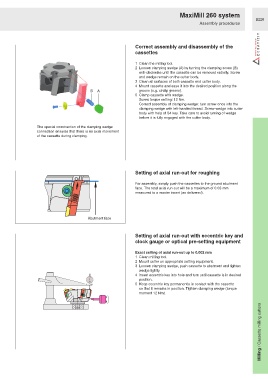
Correct assembly and disassembly of the
cassettes
1 Clean the milling tool.
2 Loosen clamping wedge (A) by turning the clamping screw (B)
anti-clockwise until the cassette can be removed radially. Screw
and wedge remain on the cutter body.
3 Clean all surfaces of both cassette and cutter body.
4 Mount cassette and ease it into the desired position along the
B A groove (e.g. circlip groove).
5 Clamp cassette with wedge.
Screw torque setting: 12 Nm.
Correct assembly of clamping wedge: turn screw once into the
clamping wedge with left-handed thread. Screw wedge into cutter
body with help of S4 key. Take care to avoid turning of wedge
before it is fully engaged with the cutter body.
The special construction of the clamping wedge
connection ensures that there is no axial movement
of the cassette during clamping.
Setting of axial run-out for roughing
For assembly, simply push the cassettes to the ground abutment
face. The total axial run-out will be a maximum of 0.03 mm
measured to a master insert (as delivered).
Abutment face
Setting of axial run-out with eccentric key and
clock gauge or optical pre-setting equipment
Exact setting of axial run-out up to 0.002 mm
1 Clean milling tool.
2 Mount cutter on appropriate setting equipment.
3 Loosen clamping wedge, push cassette to abutment and tighten
wedge lightly.
4 Insert eccentric key into hole and turn until cassette is in desired
position.
1
1000
5 Keep eccentric key permanently in contact with the cassette
so that it remains in position. Tighten clamping wedge (torque
moment 12 Nm).
Milling / Cassette milling cutters