
Page 308 - Tungaloy Catalog
P. 308
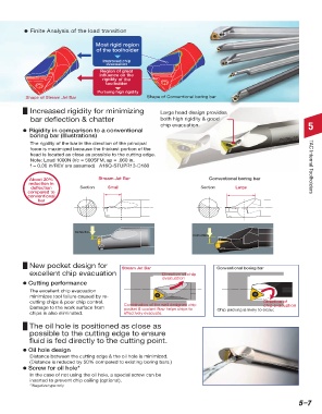
d  Finite Analysis of the load transition

                                             Most rigid region
                                              of the toolholder
                                                Improved chip
                                                 evacuation
                                               Region of great
                                               influence on the
                                                rigidity of the
                                                 toolholder
                                              Pursuing high rigidity
                   Shape of Stream Jet Bar                       Shape of Conventional boring bar

                     Increased rigidity for minimizing                Large head design provides
                     bar deflection & chatter                         both high rigidity & good
                                                                      chip evacuation.                                        5
                  d Rigidity in comparison to a conventional
                      boring bar (Illustrations)
                     The rigidity of the bar in the direction of the principal
                     force is maximized because the thickest portion of the
                     head is located as close as possible to the cutting edge.
                     Note: Load 1000N (Vc = 500SFM, ap = .060 in,
                     f = 0.00 in/REV are assumed)   A16Q-STUPR13-D180                                                          TAC Internal Toolholders

                    About 20%                 Stream Jet Bar                            Conventional boring bar
                    reduction in
                     deflection        Section    Small                              Section       Large
                    compared to
                    conventional
                       bar


                                     Deflection
                                                                                  Deflection


                    New pocket design for              Stream Jet Bar                      Conventional boring bar
                    excellent chip evacuation                          Direction of chip
                                                                       evacuation
                  d Cutting performance
                    The excellent chip evacuation
                    minimizes tool failure caused by re-
                    cutting chips & poor chip control.                                                       Direction of
                                                                                                             chip evacuation
                    Damage to the work surface from     Combination of the well designed chip   Chip packing is likely to occur.
                                                        pocket & coolant flow helps chips to
                    chips is also eliminated.           effectively evacuate.
                    The oil hole is positioned as close as
                    possible to the cutting edge to ensure
                    fluid is fed directly to the cutting point.
                  d Oil hole design
                    Distance between the cutting edge & the oil hole is minimized.
                    (Distance is reduced by 50% compared to existing boring bars.)
                  d Screw for oil hole*
                    In the case of not using the oil hole, a special screw can be
                    inserted to prevent chip coiling (optional).
                    * Negative type only


                                                                                                                          5–7