Page 309 - Tungaloy Catalog
P. 309

TAC Internal Toolholders


                    Improved tool life

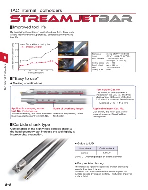
                  By supplying the optimum level of cutting fluid, flank wear
                  & rake face wear are suppressed, considerably improving
                  tool life.   Competitor's boring bar


                      0.20
                    Corner flank wear width VBc (mm)  0.15                           Toolholder  : A16Q-STUPR1103-D180
                               Stream Jet Bar


            5         0.05                                                           Work material  : 1045 SAE (220HB)
                                                                                                 : TPMT110304-PS (GT730)
                                                                                     Insert
                      0.10
                                                                                                 : Boring (1.18 - 2.00 in)
                                                                                     Cutting speed
                                                                                                 : Vc = 400
              TAC Internal Toolholders  d Marking specifications  25   30            Feed        : f = .008 in/REV
                                                                                                 : ap = .020 in
                                                                                     Depth of cut
                                                                                     Cutting fluid
                                                                                                 : Wet
                                 10
                                           20
                                      15
                        0
                             5
                                 Cutting time (min)
                    “Easy to use”
                                                                                         Tool holder Cat. No.
                                                                                         The minimum bore diameter is
                                                                                         indicated in the Cat. No. The three-
                                                                                         digit number at the end of the text
                                                                                         indicates the minimum bore diameter.
                                                                                           (Example)-D140 → 14.0 mm

                   Applicable clamping screw         Scale of overhang length         Applicable insert Cat. No.
                   Cat. No.  (Positive type only)                                     Can identify the insert size & relief
                   If screw is missing, this detail simplifies   Useful for easy setting of the   angle at a glance. Simplified tool
                   locating a replacement with Cat. No.  toolholder.                  management.

                    Carbide shank type

                  Combination of the highly rigid carbide shank &
                  the head geometry can increase the tool rigidity &
                  improve chip evacuation.


                                                                       d Guide to L/D
                                                                           Steel shank     Carbide shank

                                                                            L/D ≤ 3            L/D ≤ 5
                                                                       (Note) L : Overhang length, D: Shank diameter

                                                                       d For precision boring
                                                                       The increased rigidity suppresses chatter, producing
                                                                       excellent surface finishes.
                                                                       Excellent chip evacuation minimizes damage to the
                                                                       surface caused by chip re-cutting. This further improves
                                                                       surface finish.


             5–8
   304   305   306   307   308   309   310   311   312   313   314