
Page 1044 - Tungaloy Catalog
P. 1044
Technical Reference
Drilling Tools
Troubleshooting for TAC drills
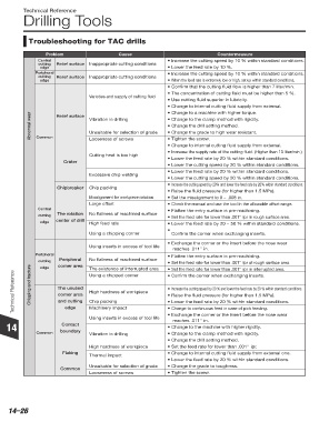
Problem Cause Countermeasure
Central • Increase the cutting speed by 10 % within standard conditions.
cutting Relief surface Inappropriate cutting conditions
edge • Lower the feed rate by 10 %.
Peripheral • Increase the cutting speed by 10 % within standard conditions.
cutting Relief surface Inappropriate cutting conditions
edge • When the feed rate is extremely low or high, set up within standard conditions.
• Confirm that the cutting fluid flow is higher than 7 liter/min.
• The concentration of cutting fluid must be higher than 5 %.
Varieties and supply of cutting fluid
• Use cutting fluid superior in lubricity.
• Change to internal cutting fluid supply from external.
• Change to a machine with higher torque.
Abnormal wear Vibration in drilling • Change to the clamp method with rigidity.
Relief surface
• Change the drill setting method.
• Change the grade to high wear resistant.
Unsuitable for selection of grade
Common
• Tighten the screw.
Looseness of screws
• Change to internal cutting fluid supply from external.
• Increase the supply rate of the cutting fluid. (Higher than 10 liter/min.)
Cutting heat is too high
• Lower the feed rate by 20 % within standard conditions.
Crater
• Lower the cutting speed by 20 % within standard conditions.
• Lower the feed rate by 20 % within standard conditions.
Excessive chip welding
• Lower the cutting speed by 20 % within standard conditions.
• Increase the cutting speed by 20% and lower the feed rate by 20% within standard conditions.
Chipbreaker Chip packing
• Raise the fluid pressure (for higher than 1.5 MPa).
Misalignment for workpiece rotation • Set the misalignment to 0 ~ .008 in.
Large offset • Check the manual and use the tool in the allowable offset range.
Central • Flatten the entry surface in pre-machining.
cutting The rotation No flatness of machined surface • Set the feed rate for lower than .001'' ipr in rough surface area.
edge center of drill High feed rate • Lower the feed rate by 20 ~ 50 % within standard conditions.
•
Using a chipping corner Confirm the corner when exchanging inserts.
• Exchange the corner or the insert before the nose wear
Using inserts in excess of tool life
reaches .011'' in.
Peripheral • Flatten the entry surface in pre-machining.
Peripheral
cutting corner area No flatness of machined surface • Set the feed rate for lower than .001'' ipr at rough surface area.
edge
• Set the feed rate for lower than .001'' ipr in interrupted area.
The existence of interrupted area
Technical Reference Chipping and fracture The unused High hardness of workpiece • Increase the cutting speed by 20 % and lower the feed rate by 20 % within standard conditions.
• Confirm the corner when exchanging inserts.
Using a chipped corner
corner area
• Raise the fluid pressure (for higher than 1.5 MPa).
and cutting
Chip packing
• Lower the feed rate by 20 % within standard conditions.
edge
Machinery impact
• Exchange the corner or the insert before the nose wear
Using inserts in excess of tool life • Change to continuous feed in case of pick feeding.
reaches .011'' in.
14 Contact • Change to the machine with higher rigidity.
Common boundary Vibration in drilling • Change to the clamp method with rigidity.
• Change the drill setting method.
High hardness of workpiece • Set the feed rate for lower than .001'' ipr.
Flaking • Change to internal cutting fluid supply from external one.
Thermal impact
• Lower the feed rate by 20 % within standard conditions.
Unsuitable for selection of grade • Change the grade to toughress.
Common
Looseness of screws • Tighten the screw.
14–26