
Page 299 - Tungaloy Catalog
P. 299
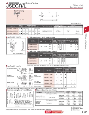
J-type / External Turning
JSEGR/L Screw-on system
Without offset
Back turning
L1
L2
f b
ap ≤ 3 mm h1 h
Dimensions (in) Applicable Clamping Screws Wrench B41 Right hand (R) shown.
Cat. No. inserts Stock Dimensions (mm) Clamping screw Wrenches
R L h b L1 L2 h1 f C Cat. No. R L h b L1 L2 h1 f Applicable inserts
JSTBR/L063 d d 0.375 0.375 0.375 0.250 0.200 JSEGR/L1010K10 d d 10 10 10 7.5
JSTBR/L083 d d 0.500 0.500 5 0.59 0.500 0.375 0.120 JTBR/L3*** CSTB-4SD T-8F (T-8L) 4
JSTBR/L103 d d 0.625 0.625 0.625 0.500 - JSEGR/L1212K10 d d 12 12 125 3.3 12 9.5 J10ER/L CSTB-2.5 T-8F (T-8L)
JSEGR/L1616K10 d d 16 16 16 13.5 *Optional
Dimensions (mm) Clamping Screws Wrench
Cat. No. Applicable Applicable inserts
R L h b L1 L2 h1 f C inserts J10E-type inserts (with sharp edges)
Stock
JSTBR/L1010K3 d d 10 10 10 6 5 0.5 Dimensions (mm) Max. Coated Coated cermet Cermet Uncoated
JSTBR/L1212K3 d d 12 12 125 15 12 8 3 JTBR3¨¨¨ CSTB-4SD T-8F - 30˚ r ε Cat. No. ød T rε depth J740 J530 NS530 TH10 TAC External Toolholders
JSTBR/L1616K3 d d 16 16 16 12 - 60˚ 3.3 of cut R L R L R L R L
J10ER/L005BF 0.05 d d d
J10ER/L010BF 6.35 3.18 0.1 3 d d d
J10ER/L015BF 0.15 d d d
ød T J10E-type inserts (with honed edges)
Right hand (R) shown. Dimensions (mm) Stock
Max.
Cat. No. ød T rε depth Coated Coated cermet Cermet Uncoated
J740
J530
NS530
TH10
of cut R L R L R L R L
J10ER/L005B 0.05
J10ER/L010B 6.35 3.18 0.1 3 d
J10ER/L015B 0.15
Applicable inserts Notes: Right hand holder use right hand insert and left hand holder use left hand insert.
W
6.35 6.35 A 5° W 26° ø3.0ø3.0 Type Cat. No. Dimensions Cermet Uncoated
With chipbreaker 6.35 W ø3.0 Stock
A A
(mm)
26°
5°
5° 13.0 26° 3.18 W A NS530 R TH10 L
13.0
3.18
L
R
13.0 3.18
10ER/L100BC 1 2.5
Without W
chipbreaker 6.35 W ø3.0 With
chipbreaker
6.35 6.35 A 5° W 13.0 26° ø3.0ø3.0 10ER/L150BC 1.5 3
A A
5°
26°
3.18
5° 13.0 26° 3.18 10ER/L100B 1 2.5
13.0 3.18 Without
Insert blank chipbreaker
6.35 ø3.0ø3.0 ø3.0 10ER/L150B 1.5 3
3.18 Insert blank
Right hand (R) shown. 6.35 6.35 3.0 13.3 3.18 10ER/L300 - -
13.3
3.0 3.0
3.18
13.3
Notes: Right hand holder (SEGR~) use right hand insert (10ER~) and left hand holder (SEGL~) use left hand insert (10EL~).
Formed examples of insert blanks Standard cutting conditions
Work materials Carbon Stainless Brass
steels
Operations
steels
Front turning Back turning Threading Grooving Lateral feed Cutting speed (SFM) Roughing ~ .002 ~ .001 ~ .004
~ 160
~ 650
~ 330
(external turning)
~ .001
~ .001
~ .002
Medium
Feed (in/rev)
Notes: Cutting speed (SFM) Finishing ~ .0007 ~ .0006 ~ .004
Parting-off angle, edge width can be ground Parting-off Feed (in/rev) Roughing ~ .0007 ~ .0006 ~ .002
~ 260
~ 100
~ 500
• Front relief angle, side relief
Grooving
depending on the application.
~ .0006
~ .001
Medium
~ .0004
• Insert blanks can be formed to a
profiling tool which has a width up Forming Finishing ~ .0004 ~ .0003 ~ .0006
to 3mm.
d : Stocked items
: Stocked items.
: Stocked in Japan
Most unmarked items are available on a RFQ basis, contact your sales rep for more information. : Discontinued
: Stocked in Japan
Relating Parts Relating Cutting conditions 4–73
pages (13-1~) pages (8-3)