
Page 301 - Tungaloy Catalog
P. 301
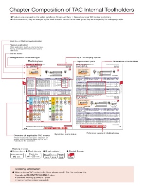
Chapter Composition of TAC Internal Toolholders
uProducts are arranged by the series as follows: Stream Jet Bars g General purpose TAC boring toolholders
uIn the same series, they are arranged by the insert shape to be used. In the same group, they are arranged by the cutting edge style.
Cat. No. of TAC boring toolholder
Typical application
Main application (such as internal turning,
facing, profiling) of the toolholder type is
illustrated.
Series name
Designation of toolholder type Type of clamping system
Machining type Replacement parts Dimensions of toolholders
S-type Positive rake / Screw-on system S-type Positive rake / Screw-on system
STUPR/L Steel Carbide SVQBR/L Steel Carbide
Shank
Shank
Shank
Shank
Boring Boring & internal profiling
ØDm h Oil Hole ØDm h
95° 117.5° Oil Hole
ØDs 25.5˚ ØDs
f f f2
f2 L2 L1 L2 L1
α α θ
U θ Cutting edge style F Right hand (R) shown.
Steel Shank (inch) Right hand (R) shown. Steel Shank (inch) Std.
Min
radius
Std.
Min Dimensions (IN) corner Applicable Parts Toolholder Cat. No. Stock bore.dia Dimensions (in) corner Applicable Parts
inserts
Stock bore.dia.
Toolholder Cat. No. radius inserts Torque R L ØDm ØDs f L1 L2 h f2 θ α rε Clamping screw Wrench
R L ØDm ØDs f L1 L2 h f2 θ α rε Clamping screw Wrench A10-SVQBR2-D16 1.00 .625 .500 7 1.25 .600 - -5 -6 .016 VBoo1103 CSTB-2.5 T-8F
A05-STUPR/L7-D07 .438 .313 .250 5.00 .625 2.88 -7˚ TPoo0902 CSTB-2.2S T-7F 0.9 Steel Shank (metric)
A06-STUPR/L2-D08 .500 .375 .281 5.00 .750 .350 -5˚ CSTB-2.5S 1.2 Min Dimensions (mm) Std. Parts
A08-STUPR/L2-D11 .688 .500 .406 5.00 1.00 .475 -3˚ .016 TPoo1102 CSTB-2.5B 1.2 Toolholder Cat. No. Stock bore.dia. corner Applicable Torque 5
radius
5 A10-STPUR/L2-D14 .875 .625 .531 7.00 1.25 .600 - 5˚ -2˚ CSTB-2.5 T-8F 1.4 A12M-SVQBR/L11-D170 R L ØDm ØDs 12 10.5 150 L1 L2 24 11 h 4.5 f2 -5˚ θ -10˚ α 0.4 rε inserts Clamping screw Wrench (N·m)
f
17
A10-STUPR/L2.5-D14 .875 .625 .531 7.00 1.25 .600 -2˚ TPoo1103 1.4 A16Q-SVQBR/L11-D215 21.5 16 13 180 30 15 5 -5˚ -8˚ 0.4 VBoo1103 CSTB-2.5 T-8F 1.2
A12-STUPR/L3-D16 1.00 .750 .594 7.00 1.437 .725 -2˚ 0˚ .032 TPoo16T3 CSTB-4M T-15F 1.4 3.0 A20R-SVQBR/L11-D255 25.5 20 25 17.5 250 36 45 18 23 5 5 -5˚ -5˚ -6˚ -8˚ 0.4 0.8 VBoo1604 CSTB-3.5 T-15F 3.0
15
200
A16-STUPR/L3-D20
TAC Internal Toolholders Carbide Shank (inch) R L ØDm ØDs f L1 Dimensions (IN) f2 θ -7˚ -5˚ α corner Applicable Clamping screw Wrench Torque E12Q-SVQBR/L11-D170 Stock L bore.dia. ØDs 12 16 20 10.5 180 L1 Dimensions (mm) 4.5 f2 5 5 -5˚ -5˚ -5˚ θ -10˚ α corner rε VBoo1103 Clamping screw Wrench Torque TAC Internal Toolholders
1.25
1.00 .688 7.00 1.75 .975
30.5
A25S-SVQBR/L16-D305
Carbide Shank (metric)
Std.
Min
Parts
Applicable
Toolholder Cat. No.
Std.
inserts
(N·m)
radius
Min
Parts
h
ØDm
f
L2
R
Stock bore.dia.
Toolholder Cat. No.
inserts
radius
27
0.4
h
17
L2
11
rε
T-8F
E16R-SVQBR/L11-D215
E05-STUPR7-D07
21.5
.313 .250 5.00 .625 2.88
32
1.2
0.4
200
0.9
-8˚
13
CSTB-2.5
TPoo0902 CSTB-2.2S T-7F
.438
15
E06-STUPR2-D08
CSTB-2.5S
250
15
0.4
-6˚
.500
1.2
25.5
36
E20S-SVQBR/L11-D255
18
.375 .281 5.00 .750 .350
.016 TPoo1102
T-8F
5˚
-
25
17.5 300
CSTB-2.5B
23
45
E08-STUPR2-D11
E25T-SVQBR/L16-D305
5
-3˚
.500 .406 5.00 1.00 .475
30.5
1.2
.688
T-9F
1.4
When using a right or left hand insert, the right hand insert (R) is used for the left hand toolholders
.625 .531 7.00 1.25 .600
.875
-2˚
CSTB-3
E10-STUPR2.5-D14
TPoo1103
(SVQBL type), and the left hand insert (L) is used for the right hand toolholders (SVQBR type). -5˚ -8˚ 0.8 VBoo1604 CSTB-3.5 T-15F 3.0
S-type Positive rake / Screw-on system
Basic Selection Chipbreakers TPoo1102oo-oo
Precision Finishing to Precision Finishing to SVUBR/L Steel Carbide
Operation finishing Finishing medium cutting Medium cutting Operation finishing Finishing medium cutting Medium cutting Shank Shank
Grade NS9530 AH725 T9115 T9125 Grade GH330 AH725 AH725 T6130
Page 2-123 2-123 2-125 2-128 Page 2-124 2-123 2-126 2-128
01 PSF PS PM W15 PSF PSS PM
Boring & internal profiling
Chipbreaker Chipbreaker ØDm h
Steel Stainless 50˚ L2 Clamping screw Oil Hole
Vc (SFM) (500-800) (170-600) (400-800) (400-800) Vc (SFM) (100-150) (150-600) (150-600) (250-400)
Continuous ap (in) (.001-.006) (.005-.030) (.010-.060) (.040-.118) Continuous ap (in) (.001-.080) (.005-.030) (.010-.060) (.040-.118) 93° f ØDs 93° ØDs
f (in/rev) (.001-.006) (.001-.006) (.002-.008) (.003-.012) f (in/rev) (.001-.006) (.001-.006) (.002-.008) (.003-.012) f2 f
rε (in) .016 .016 .032 .032 rε (in) .016 .016 .032 .032
L1 f2
Finishing to
L1
Operation Precision medium cutting Medium cutting Operation Precision Finishing U α θ Carbide Shank style
finishing
finishing
Grade BX930 T5115 T5115 Grade DX140 GH110 Cutting edge style
Page 3-14 2-130 2-131 Page 3-24 2-124 Steel Shank (inch)
T-CBN CM No chipbreaker T-DIA W15 Right hand (R) shown.
Std.
Stock Min Dimensions (in) corner Parts
Chipbreaker Chipbreaker Toolholder Cat. No. bore.dia radius Applicable
Cast lron Non-ferrous R L ØDm ØDs f L1 L2 h f2 θ α rε inserts Clamping screw Wrench
Vc (SFM) (600-1400) (450-1300) (450-1300) Vc (SFM) (800-4000) (300-3000) A12-SVUBR2-D16 1.00 .750 .594 10 1.425 .725 - -0 -6 .016 VBoo1103 CSTB-2.5 T-8F
Continuous ap (in) (.001-.006) (.001-.080) (.001-.080) Continuous ap (in) (.001-.020) (.001-.080) Steel Shank (metric)
f (in/rev) (.001-.008) (.001-.008) (.001-.008) f (in/rev) (.001-.008) (0.0.3-0.15)
rε (in) .016 .032 .032 rε (in) .016 .016 Stock Min Dimensions (mm) Std. Parts
inserts
(N·m)
radius
ØDm
Operation Precision Finishing Operation Precision Finishing Toolholder Cat. No. R L bore.dia. ØDs f L1 L2 h f2 θ α corner rε Applicable Clamping screw Wrench Torque
finishing
finishing
Grade BX470 BX950 Grade BXM10 BXM20 A16Q-SVUBR/L11-D200 20 16 15.5 180 35 15 8 0˚ -8˚ 0.4
Page 3-12 3-14 Page 3-12 3-12 VBoo1103 CSTB-2.5 T-8F 1.2
T-CBN T-CBN T-CBN T-CBN A20R-SVUBR/L11-D250 25 20 17.5 200 40 19 8 0˚ -7˚ 0.4
Chipbreaker Chipbreaker A25S-SVUBR/L16-D320 32 25 20.5 250 50 23 8.5 0˚ -6˚ 0.8 VBoo1604 CSTB-3.5 T-15F 3.0
Hard
Superalloys Materials Carbide Shank (metric)
Vc (SFM) (300-800) (230-900) Vc (SFM) (500-1100) (400-750) Stock Min Dimensions (mm) corner Parts Torque
Std.
inserts
Continuous ap (in) (.001-.006) (.005-.030) Continuous ap (in) (.001-.008) (.001-.008) Toolholder Cat. No. R L bore.dia. ØDs f L1 L2 h f2 θ α radius Applicable Clamping screw Wrench (N·m)
f (in/rev) (.001-.008) (.001-.008) f (in/rev) (.0001-.003) (.001-.006) ØDm rε
rε (in) .016 .016 rε (in) .016 .016 E16R-SVUBR/L11-D245 24.5 16 16 200 - 15 8 0˚ -8˚ 0.4
For other machining types, see “Selection System” 2-18~ E20S-SVUBR/L11-D285 28.5 20 18 250 - 19 8 0˚ -7˚ 0.4 VBoo1103 CSTB-2.5 T-8F 1.2
E25T-SVUBR/L16-D340 34 25 21 300 - 23 8.5 0˚ -6˚ 0.8 VBoo1604 CSTB-3.5 T-15F 3.0
When using a right or left hand insert, the right hand insert (R) is used for the left hand toolholders
(SVUBL oo type), and the left hand insert (L) is used for the right hand toolholders (SVUBR oo type). : Stocked items.
: Stocked in Japan
Most unmarked items are available on a RFQ basis, contact your sales rep for more information.
: Stocked items. Features Relating Sleeves Parts 5–27
Most unmarked items are available on a RFQ basis, contact your sales rep for more information. (5-6) pages (5-64~) (13-1~)
Parts
5–26 Features Relating Sleeves (13-1~)
(5-64~)
pages
(5-6)
Applicable TAC inserts
Reference pages of relating items
Symbol of stock status
Overview of applicable TAC inserts
These charts indicate basic selection of
grades and chipbreaker types by the work
material and the application.
■ Meaning of icons
d Min. bore diameter d Shank diameter d Shank material d Coolant through
Min. bore dia. Shank dia. Steel Carbide Tsuppari-
Ichiban
ø5 mm ø4~25 mm Shank Shank Shank Oli Hole
■ Ordering information
d When ordering TAC boring toolholders, please specify Cat. No. and quantity.
Example: A16Q-STUPR1103-D180 1 piece
• Standard packing quantity is 1 piece
• Inserts must be ordered separately.