
Page 329 - Tungaloy Catalog
P. 329
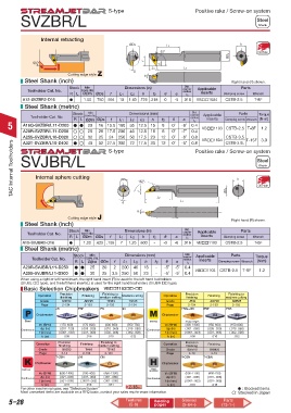
S-type Positive rake / Screw-on system
SVZBR/L Steel
Shank
Internal retracting
ØDm L2 h
93° Oil Hole
ØDs
50˚ f f2
L3 L1
Cutting edge style Z α θ
Steel Shank (inch) Right hand (R) shown.
Std.
Stock Min Dimensions (in) corner Applicable Parts
Toolholder Cat. No. bore.dia radius
R L ØDm ØDs f L1 L2 h f2 θ α rε inserts Clamping screw Wrench
-
A12-SVZBR2-D16 d 1.00 .750 .594 10 1.43 .725 .218 0 -5 .016 VBoo1604 CSTB-2.5 T-8F
Steel Shank (metric)
Std.
Min
Stock bore.dia. Dimensions (mm) corner Applicable Parts Torque
Toolholder Cat. No. R L ØDm ØDs f L1 L2 L3 h f2 θ α radius inserts Clamping screw Wrench (N·m)
rε
5 A16Q-SVZBR/L11-D200 d d 20 16 15.5 180 35 12.5 15 8 0˚ -8˚ 0.4 VBoo1103 CSTB-2.5 T-8F 1.2
A20R-SVZBR/L11-D250 25 20 17.5 200 40 12.5 18 8 0˚ -7˚ 0.4
24
250
CSTB-3.5
A25S-SVZBR/L16-D320 d 32 25 S-type 50 17.5 23 12 0˚ -6˚ 0.8 Positive rake / Screw-on system
T-15F 3.0
VBoo1604
TAC Internal Toolholders SVJBR/L ØDm 142° h Steel
0.8
72 17.5 30
40
-5˚
0˚
32 27.5 300
A32T-SVZBR/L16-D400
12
CSTB-3.5L
Shank
Internal sphere cutting
f
L2 ØDs Oil Hole
α L1
θ
Cutting edge style J Right hand (R) shown.
Steel Shank (inch)
Std.
Stock Min Dimensions (in) corner Applicable Parts
Toolholder Cat. No. bore.dia radius
R L ØDm ØDs f L1 L2 h f2 θ α rε inserts Clamping screw Wrench
A10-SVJBR2-D16 d 1.00 .625 .156 7 1.25 .600 - -5 -6 .016 VBoo1103 CSTB-2.5 T-8F
Steel Shank (metric)
Std.
Stock Min Dimensions (mm) corner Applicable Parts Torque
Toolholder Cat. No. bore.dia. radius inserts
R L ØDm ØDs f L1 L2 h f2 θ α rε Clamping screw Wrench (N·m)
A20R-SVJBR/L11-D250 d d 25 20 2 200 40 18 - -5˚ -5˚ 0.4 VBoo1103 CSTB-2.5 T-8F 1.2
A25S-SVJBR/L11-D300 d d 30 25 3.5 250 50 23 - -5˚ -5˚ 0.4
When using a right or left hand insert, the right hand insert (R) is used for the left hand toolholders
(SVJBL oo type), and the left hand insert (L) is used for the right hand toolholders (SVJBR oo type).
Basic Selection Chipbreakers VBoo1103oo-oo
Precision Finishing to Precision Finishing to
Operation finishing Finishing medium cutting Medium cutting Operation finishing Finishing medium cutting
Grade SH730 AH725 T9115 T9125 Grade J740 AH725 AH725
Page 2-134 2-133 2-133 2-134 Page 2-134 2-133 2-133
JS PSF PS 24 FR/L-J10 PSF PSS
Chipbreaker Chipbreaker
Steel Stainless Sharp edges
Vc (SFM) (170-600) (170-600) (400-850) (350-750) Vc (SFM) (400-1300) (150-600) (150-600)
Continuous ap (in) (.001-.120) (.005-.030) (.010-.060) (.015-.080) Continuous ap (in) (.001-.080) (.005-.030) (.010-.060)
f (in/rev) (.0001-.003) (.001-.006) (.002-.008) (.002-.008) f (in/rev) (.0001-.003) (.001-.006) (.002-.008)
rε (in) .008 .016 .016 .032 rε (in) .008 .016 .032
Finishing to
Operation Precision Finishing medium cutting Operation Precision Finishing
finishing
finishing
Grade BX930 TH10 T5115 Grade BXM10 BXM20
Page 3-14 2-134 2-133 Page 3-13 3-13
T-CBN J10 CM T-CBN T-CBN
Chipbreaker Chipbreaker
Hard
Cast lron Materials
Vc (SFM) (600-1400) (100-400) (450-1300) Vc (SFM) (500-1100) (400-750)
ap (in) (.001-.006) (.001-.080) (.001-.080) ap (in) (.001-.006) (.001-.006)
Continuous Continuous
f (in/rev) (.001-.008) (.0001-.003) (.001-.008) f (in/rev) (.0001-.003) (.001-.006)
rε (in) .016 .016 .031 rε (in) .016 .016
For other machining types, see “Selection System” 2-18~ : Stocked items.
Most unmarked items are available on a RFQ basis, contact your sales rep for more information. : Stocked in Japan
Parts
5–28 Features Relating Sleeves (13-1~)
(5-64~)
(5-6)
pages