
Page 414 - Tungaloy Catalog
P. 414
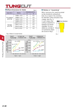
Offset dimensions for blade              Table 1         Notice in “traversing”
                                          Dimensions (mm)         When traversing, the insert is pushed
            Application     Blades
                                           A         B            by the directional cutting force
                         CAER/L-3T16      16        10.4          feed. As a result of this condition
           For external  CAER/L-4T16      16        10.5          the diameter of the workpiece may
             grooving    CAER/L-5T20      20        10.5          change. (see Fig. 1)
                         CAER/L-6T20      20        10.5          In such cases, trial         Feed direction
                        CAFR/L-3T12-*     12        10.4          cutting is essential to
             For face   CAFR/L-4T16-*     16        10.5          measure the actual
             grooving   CAFR/L-5T20-*     20        10.5          diameter. For your
                        CAFR/L-6T20-*     25        10.5          reference, sample of    A’  A
                                                                  compensated values
                                                                  are shown in Fig.2.
           Fig. 2 Value of compensation                                                  Fig. 1
                 Insert     :  DTE300-040      Insert     :  DTE400-040
    6            Toolholder  :  CTER2525-3T09    Toolholder  :  CTER2525-4T10
              0.010  ap = 0.118"             0.010   ap = 0.118"  ap = 0.078"
                        ap = 0.078"
      Parting and Grooving Tools  Outer diameter compensation (inch)  0.006 0   0.004  0.008  0.012  0.016  0.020 0.024 Outer diameter compensation (inch)  0.006 0   0.004  0.008  0.012  0.016  0.020 0.024
                                             0.008
              0.008
                                                              ap = 0.039"
                               ap = 0.039"
                                             0.004
              0.004
                                                              ap = 0.020"
                               ap = 0.020"
              0.002
                                             0.002
                       Feed : f  (ipr)
                                                      Feed : f  (ipr)


     6–34