
Page 45 - Tungaloy Catalog
P. 45
(ISO) Designation
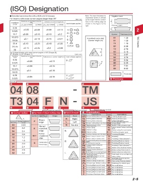
d Detailed accuracy for J,K,L,M,N and U classes Note: The insert thickness for Negative insert
chipbreaker inserts is defined
For inserts with nose corner angles larger than 55˚ Unit: mm as the height from the bottom
Tolerance on inscribed circle dia. Tolerance on corner height (m) face to the cutting edge as s
Inscribed (ød) Insert shapes applied
circle J,K,L,M,N (class) U (class) J,K,L,M,N (class) U (class) shown in the figure to the
right. Positive insert
6.35
2 9.525 ±0.05 ±0.08 ±0.08 ±0.13 H W s 2
12.7 ±0.08 ±0.13 ±0.13 ±0.2 O R Symbol Thickness (mm)
15.875 P X1 1.39
±0.1 ±0.18 ±0.15 ±0.27 Inscribed circle (ød)
19.05 S Corner height (m) 01 1.59
25.4 ±0.13 ±0.25 ±0.18 ±0.38 T T1 1.79 TAC Inserts
31.75 ±0.15 ±0.25 ±0.2 ±0.38 C,E,M 02 2.38
TAC Inserts
32 T2 2.78
For M-type inserts with nose corner angles of 55˚ (Shape: D), ød m 03 3.18
35˚ (Shape: V), 25˚ (Shape: Y) Unit: mm T3 3.97
Inscribed Tolerance on inscribed circle dia. Tolerance on corner height (m) Insert shapes applied
circle (ød) 04 4.76
6.35 ±0.05 ±0.11 D 05 5.56
9.525 ød m 06 6.35
12.7 ±0.08 ±0.15 07 7.94
15.875 ±0.1 ±0.18 09 9.52
19.05
Thickness
6.35 ±0.05 ±0.16 V
9.525 Y 6 Thickness
[Example] 7 10
6
04 08 - TM
T3 04 F N - JS
6 7 8 9 10
(Optional symbol) (Optional symbol) (Supplementary symbol)
7 Corner radius 8 Symbols of major cutting edge 9 Hand of insert 10 Chipbreakers
Applications
Symbol Condition of Shape Symbol Hand Symbol Applications Symbol Finishing (Angular type)
W
cutting edge
01(TF) Precision finishing (Basic selection)
r ε Sharp R Right TS Finishing (Basic selection) PSF Finishing (Positive type)
PS
(Positive type Basic selection)
Symbol Corner radius rε F edge L Left TSF Finishing (Basic selection) PSS Finish to light cutting
(mm)
TM
Finish to Medium cutting
Medium cutting (Basic selection)
00 0.03 N Neutral TH Medium to heavy cutting PM (Positive insert)
Medium cutting (Positive type)
Honed (Basic selection)
02 0.2 E rounded TU Heavy cutting AL Finish to Medium cutting of aluminium
alloys
RS
DM
Medium cutting
Medium cutting (For round inserts)
04 0.4 edge N HMM Medium cutting Whh Finishing (Angular type)
08 0.8 W.T Honed SS Finishing of stainless and mild steels Hhh Finishing (Parallel)
12 1.2 chamfered SM Medium cutting of stainless steels 11 Finishing
edge
17
Finishing (“Zebra breaker”)
S
Medium cutting of stainless steels
16 1.6 R SA For heat-resisting alloys and stainless 23 Finishing (Positive insert)
steels
20 2.0 S Combination ZF Finishing and copying 24 Finishing (Positive insert)
honed edge
Finish to medium cutting and
24 2.4 ZM copying 27 Finishing (“Zebra breaker”)
33
NS
Finishing and copying
Medium cutting (Toughness breaker)
28 2.8 NM Finish to medium cutting and 37 Medium cutting (“Zebra breaker”)
copying
32 3.2 L AS Small depth of cut and high feed 38 Medium cutting (Low cutting force)
AFW Small depth of cut and high feed 51 Small depth of cut and high feed
(Wiper type Inserts)
ASW Small depth of cut and high feed 57 Heavy cutting
(Wiper type Inserts)
CB Medium cutting 61 Small depth of cut and high feed
(For round inserts)
CM Medium cutting of cast irons 65 Heavy cutting (Three step breaker)
All- All-round type. Medium cutting S1
round Finishing (For KNMX type)
A Finishing (Right and left hand) J08,J10 For small lathes
B Finishing (Right and left hand) JS For small lathes
C Finishing (Right and left hand) JRP For small lathes
D Finishing (Right and left hand) JPP For small lathes
P Finishing of Aluminium alloys JSP For small lathes
2–4 2–5