
Page 44 - Tungaloy Catalog
P. 44
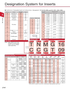
Designation System for Inserts
Conforms to “Indexable Inserts for Cutting Tools - Designation” (JIS B4120-1998, and ISO 1832 / AM1-1998)
Symbol Shape Nose angle Figure Symbol Corner height (m) Tolerance (mm) I. C. dia. (ød)
(degree)
(class)
Thickness (s)
2 H Hexagonal 120° A ±0.005 ±0.025 ±0.025
O
Octagonal
135°
P Pentagonal 108° Symbol Relief angle F ±0.005 ±0.025 ±0.013
±0.025
C
±0.013
±0.025
S
Square
90°
TAC Inserts T Triangular 60° A 3° H ±0.013 ±0.025 ±0.013
±0.025
±0.025
E
±0.025
80°
C
5°
B
±0.025
±0.13
G
±0.025
D
7°
D
E Rhombic 55° C 15° J ±0.005 ±0.025 ±0.005 ~
75°
±0.13
F 50° E 20° ±0.05 ~
M 86° F 25° K ±0.013 ±0.025 ±0.13
V 35° G 30° L ±0.025 ±0.025 ±0.05 ~
Y Y-shape (Tungaloy’s symbol) 25° N 0° ±0.13
W Trigon 80° P 11° M ±0.08 ~ ±0.13 ±0.05 ~
L Rectangular 90° O Others ±0.18 ±0.13
±0.08 ~
A 85° N ±0.18 ±0.025 ±0.05 ~
±0.13
B Parallelogram 82° ±0.13 ~ ±0.08 ~
K 55° U ±0.38 ±0.13 ±0.25
R Round - 2 Relief angle 3 Accuracy
1 Shape
1 2 3 4 5
Notes : With respect to the nose
angles of rhombic and
parallelogram shaped T N M G 16
inserts, use the smaller
angle respectively.
[Example]
C C G T 09
[Example]
1 2 3 4 5
R R R S S S C C C W W WT T T
4 Groove and hole 5 Cutting edge length
Chip-
S
Symbol Hole Shape of hole breaker Shape * R R S R S R R S C S C C W C W W T W T W T T T D D D V V V K K K I. C.dia.
C
N N Without Symbol Length Symbol Length Symbol Length Symbol Length Symbol Length Symbol Length Symbol Length Symbol Length (mm)
R R Without - Single- D D 03 D3.97 V 03 4.0 V K K K K 06 6.9 04 4.8 3.97
D
VD
V
V
sided
K
F F Double- * 05 5 04 4.76 04 4.8 - - 08 8.2 05 5.8 08 8.3 - - 4.76
sided
-
-
-
5
-
-
-
-
-
-
-
A A Without 05 5.56 05 5.6 03 3.8 09 9.6 06 6.8 5.56
Cylindrical
M M Single- * 06 6 - - - - - - - - - - - - - - 6
sided
hole
GG Double- 06 6.35 06 6.5 04 4.3 11 11 07 7.8 11 11.2 6.35
sided
7.94
09 9.7
07 7.94 08 8.1 05 5.4 13 13.8
W
W Partly cylindrical Without * 08 8 - - - - - - - - - - - - - - 8
hole, single-side
40° ~ 60°
T T Counter sink Single- 09 9.525 09 9.525 09 9.7 06 6.5 16 16.5 11 11.6 16 16.6 16 19.7 9.525
sided
QQ With Partly cylindrical Without * 10 10 - - - - - - - - - - - - - - 10
hole, double-side * 12 12 - - - - - - - - - - - - - - 12
40° ~ 60°
UU Counter sink Double- 12 12.7 12 12.7 12 12.9 08 8.7 22 22 15 15.5 22 22.1 12.7
sided
B B Partly cylindrical Without 15 15.875 15 15.875 16 16.1 10 10.9 27 27.5 19 19.4 15.875
hole, single-side
-
-
-
-
-
16
70° ~ 90°
HH Counter sink Single- * 16 16 - - - - - 13 33 33 23 23.3 - - - - 19.05
sided
19 19.05 19 19.05 19 19.3 13
CC hole, double-side Without * 20 20 - - - - - - - - - - - - - - 20
Partly cylindrical
70° ~ 90°
J J Counter sink Double- 22 22.225 22 22.6 38 38.5 27 27.1 22.225
sided
X X - - - * 25 25 - - - - - - - - - - - - - - 25
25 25.4 25 25.4 25 25.8 44 44 31 31 25.4
31 31.75 31 31.75 32 32.2 55 55 38 38.8 31.75
* 32 32 - - - - - - - - - - - - - - 32
* When M0 is included in the Cat. No., the inscribed-circle diameter is metric size.
2–4