


Page 914 - Tungaloy Catalog
P. 914
Feature

          - Easy adjustment for correcting misalignment between drill and
             workpiece on a lathe.
          - Improves cutting accuracy and tool life due to highly precise installation.
          - Increases the cutting speed and feed rate by accurate adjustment
            Reduces the total machining time.
          - Reduces damage and prolongs the tool life.

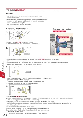
          Operating Instructions                                             Range of correction


          1.                                                                   T.I.R. max .0008"


                                                                                    Angular Adj.max 1°


          ① Install                             in the turret of lathe.
          ② Tighten the screw of No.1 and No.2 (3PC) completely.


          2.


                                                                                       Radial Adj.max D2.0mm


          ① Insert the gauge pin (No.5) through ER collet of                            and tighten the nut (No.7)
              (Use the special wrench only)
      Tooling Systems  ② Loosen each No.1, No.2 (3PC) screw until the nose piece of set ring of No.3 (for angle adjustment) and No.4
              move freely. (Refer to item 4 for the position of No.3 set ring.)
          3.


   12


          ① Hold a soft material with the chuck of the lathe and process it to tolerance h5.
              (the same diameter as No.5 gauge pin)
              The length of the processed part should be 1/2 of the gauge pin.
          ②  Place the test bush of No.6 on the processed material.
          4.


          ① Set                          on the turret.
          ② Keep the distance between the gauge pin (No.5) and the test bushing (No.6) for .197"~.394" and move it to 0 point.
               (Drill processing point of X = 0 or position of main axis)
          ③ Move the Z axis of the turret and insert the test bar (No.5) into the test bush (No.6)
              As for the inserted amount, the spaces between the roller end faces of test bush (No.6) and clamping nut (No.7)
              should be set for .394"
          ④ Confirm if the test bushing (No.6) moves freely.
          ⑤ Lightly tighten the screw (No.1) until the test bushing (No.6) barely moves.
          ⑥ Adjust the setting (No.3) so that the test bush (No.6) may move smoothly.
          ⑦ Tighten the 3 screws (No.2)
              The correction is completed if the test bushing (No.6) moves smoothly.
     12–6

