
Page 569 - Ceratizit Catalog
P. 569
Surface quality
B242
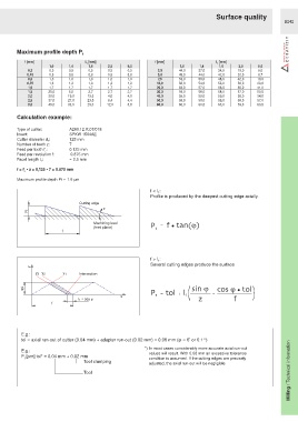
Maximum profile depth P
t
f [mm] l 1 [mm] f [mm] l 1 [mm]
1,0 1,4 1,6 2,5 9,0 1,0 1,4 1,6 2,5 9,0
0,3 0,5 0,5 0,5 0,5 0,5 3,5 44,0 37,0 34,0 19,0 6,0
0,45 0,8 0,8 0,8 0,8 0,8 5,0 49,0 44,0 42,0 32,0 8,7
0,6 1,0 1,0 1,0 1,0 1,0 7,5 53,0 50,0 48,0 42,0 13,0
0,75 1,3 1,3 1,3 1,3 1,3 12,0 56,0 54,0 53,0 50,0 23,0
1,0 1,7 1,7 1,7 1,7 1,7 20,0 58,0 57,0 56,0 55,0 41,0
1,5 20,0 5,0 2,7 2,7 2,7 30,0 59,0 58,0 58,0 57,0 50,0
2,0 30,0 19,0 13,0 4,0 4,0 40,0 59,0 59,0 59,0 58,0 54,0
2,5 37,0 27,0 23,0 6,4 4,4 50,0 59,0 59,0 59,0 59,0 57,0
3,0 40,0 33,0 29,0 12,0 5,0 60,0 60,0 60,0 60,0 59,0 60,0
Calculation example:
Type of cutter: A260.12.R.07/018
Insert: SPKW 1504AE
Cutter diameter d : 125 mm
1
Number of teeth z: 7
Feed per tooth f : 0.125 mm
z
Feed per revolution f: 0.875 mm
Facet length l : ≈ 2.5 mm
1
f = f • z = 0,125 • 7 = 0.875 mm
z
Maximum profile depth Pt ≈ 1.6 µm
f < l :
1
Profile is produced by the deepest cutting edge axially.
Cutting edge
Machining level
(feed plane) P t = f tan( )
f > l :
1
Several cutting edges produce the surface
Intersection
P t = tol l+ 1 ( sin - cos tol )
z f
E.g.:
tol ≈ axial run-out of cutter (0.04 mm) + adapter run-out (0.02 mm) = 0.06 mm (φ ≈ 6’ or 0.1°)
Milling / Technical information
*) In most cases considerably more accurate axial run-out
E.g.:
values will result. With 0.06 mm an excessive tolerance
P [µm] tol* = 0.04 mm + 0.02 mm condition is assumed. If the cutting edges are precisely
t
Tool clamping
adjusted, the axial run-out will be negligible.
Tool