
Page 224 - Parlec Catalog
P. 224
Twin Bore Roughing System
222 Adjusting for Balanced Cutting
ADJUSTING FOR BALANCED CUTTING:
Balanced cutting allows both cutting edges to work simultaneously. A properly
balanced twin cutter may be fed at almost four times the rate of a single cutter.
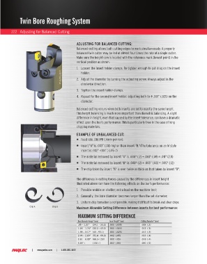
Make sure the height cam is located with the reference mark (lowest point) in the
vertical position as shown.
1. Loosen the insert holder clamps. Re-tighten enough to put drag on the insert
holder.
2. Adjust the diameter by turning the adjusting screw. Always adjust in the
clockwise direction.
3. Tighten the insert holder clamps.
4. Repeat for the second insert holder, adjusting both to ± .001” (.025) on the
diameter.
Balanced cutting occurs when both inserts are set to exactly the same height.
This height balancing is much more important than diametric balancing. A slight
difference in height, even that caused by the insert tolerance, can have a dramatic
effect upon the tool's performance. This is particularly true in the case of long
chipping materials.
EXAMPLE OF UNBALANCED CUT:
Feed rate .016 IPR (.4mm per rev).
Insert "A" is .003” (.08) higher than insert "B."(The tolerance on an M style
insert is .002”-.004”.) (.05-.1)
The material removed by insert "A" is .008" (.2) + .003" (.08) = .011" (2.8)
The material removed by insert "B" is .008" (.2) + .003” (.08) = .005" (.12)
The chip taken by insert "A" is over twice as thick as that taken by insert "B".
The difference in cutting forces caused by the differences in insert height
illustrated above can have the following effects on the bar's performance:
1. Possible wobble or chatter; extra load on the machine tool;
2. Generally, the bore diameter becomes larger than the set diameter;
3. Uniform chip formation is not possible, making it difficult to break and clear chips.
Chip A Chip B Maximum Allowable Setting Difference between inserts for best performance:
MAXIMUM SETTING DIFFERENCE
Bore Diameter Range” (mm) Insert Height” (mm) Cutting Diameter” (mm)
.95 – 1.31” (24.1 - 33.3) .001 (.025) .008 (.2)
1.26 – 1.74” (32.3 - 43.2) .001 (.025) .012 (.3)
1.58 – 2.17” (40 - 55.1) .001 (.025) .012 (.3)
2.06 – 2.83” (52.4 - 69.3) .002 (.05) .016 (.4)
2.61 – 6.00” (66.3- 150) .002 (.05) .016 (.4)
6.00”+ (150+) .002 (.05) .020 (.5)
| www.parlec.com | 1-800-866-5872