


Page 892 - Tungaloy Catalog
P. 892
Regrinding Procedures

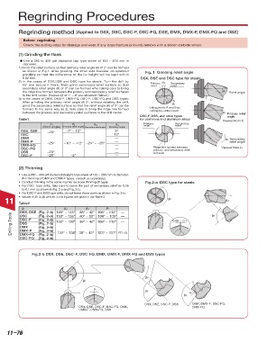
                  Regrinding method [Applied to DSX, DSC, DSC-F, DSC-FQ, DSE, DMX, DMX-F, DMX-FQ and DSS]
                    Before  regrinding
                       Check the cutting edge for damage and wear. If any large fracture is found, remove with a silicon carbide wheel.
                  (1) Grinding the flank
                  	d	Use a 280 to 400 grit diamond cup type wheel of 100 ~ 200 mm in
                    diameter.
                  1) Grind the relief surface so that primary relief angle (θ) of 2° can be formed
                   as shown in Fig.1. After grinding the other side likewise, do sparkout   Fig. 1  Grinding relief angle
                   grinding so that the difference of the lip height will be kept within
                   0.02 mm.                                              DSX, DSE and DSC type for steels
                  2) In the cases of DSX,DSE and DSC type for steels: Turn the drill by   Primary   θ4  Secondary
                   θ4° and secure it there. Then grind secondary relief surface so that   relief  relief
                   secondary relief angle (θ) of 3° can be formed whie taking care to bring
                   the ridge line formed between the primary and secondary relief surfaces                     θ1  Point angle
                   to the drill center. (Values (θ) of 1° ~ 4° are shown in Table1.)
                  3) In the cases of DMX, DMX-F, DMX-FQ, DSC-F, DSC-FQ and DSS types:                     C
                   After grinding the primary relief angle (θ) 2°, without rotating the drill,   A
                                                                                        B
                   grind the secondary relief surface so that the relief angle (θ) of 3° can be   Using points A and B as
                   formed. In the same way as 2), take care to bring the ridge line formed   reference, obtain level.
                   between the primary and secondary relief surfaces to the drill center.                      θ2  Primary relief
                                                                         DSC-F, DSS, and other types             angle
                  Table1.                                                for cast irons and aluminum alloys    Viewed from C.
                                θ 1       θ 2       θ 3       θ 4          Primary       Secondary
                                                                                         relief
                                                                           relief
                             (Point angle)    (Primary relief angle)  (Secondary relief angle)   (Rotating angle)
                      DSX, DSE  –20°   –7° ~ 10°              5°

                      DSC                                    12°
                      DMX                                     ––                                                θ3 Secondary

                      DMX–F    –25°   –10° ~ –12°  –24° ~ –26°  ––                                                relief angle


                      DMX–FQ                                  ––
                      DSC–FQ                                  ––               Ridge line formed between       Viewed from C.
                                                                               primary  and secondary relief
                      DSS      –20°                           ––               surfaces
                      DSC–F    –25°      –2°                  ––
                  (2) Thinning
                  •   Use a 280 ~ 400 grit diamond straight-type wheel of 100 ~ 200 mm in diameter.
                   (For thinning of DMX and DMX-F types, consult us separately.)
                  •   Conduct thinning in the same manner as cross thinning (X-type).  Fig.2-a  DSC type for steels
                  •   For DSC  type drills, take care to leave the part of secondary relief by 0.05
                   to 0.1 mm as shown in Fig. 2-a and Fig. 2-b.
                  •   For DSC-F and DSS type drills, do not leave those parts as shown in Fig. 2-b.
                  •   Values of β1 to β3 written in the figures are given in the Table 2.
           11     Table2.                                                             β1                         β2
                    β 1                β 2      β 3       R
                   DSX, DSE   (Fig. 2–b)  140° ~ 145°   38° ~ 42°  108° ~ 112°   ––                       β3
              Drilling Tools   DSC–F  (Fig. 2–b)  132° ~ 138°   38° ~ 42°  108° ~ 112°   ––  0.05 ~ 0.1
                   DSC
                                             40° ~ 50°  100° ~ 105°  ––
                           (Fig. 2–a)
                                   150° ~ 156°
                   DSS
                           (Fig. 2–b)
                           (Fig. 2–b)
                   DMX

                   DMX–F
                           (Fig. 2–b)

                   DMX–FQ
                   DSC–FQ  (Fig. 2–b)  132° ~ 138°  38° ~ 42°  123° ~ 127°  R1~5
                           (Fig. 2–b)
                        Fig.2-b DSX, DSE, DSC-F, DSC-FQ, DMX, DMX-F, DMX-FQ and DSS types
                                                                            β2
                                               β1
                                                    0
                                                                            β3
                                                                                                R
                                                                                             β3
                                                                           DSX, DSE, DSC-F, DSS  DMX, DMX-F, DSC-FQ,
                                             DSX, DSE, DSC-F, DSC-FQ, DMX,                       DMX-FQ
                                             DMX-F, DMX-FQ, DSS


            11–76

