Page 170 - Parlec Catalog
P. 170

Evolution Angle Heads


        168   Stop-Block Mounting Example

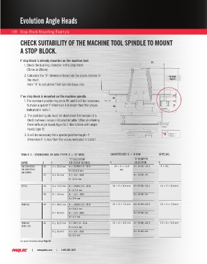
              CHECK SUITABILITY OF THE MACHINE TOOL SPINDLE TO MOUNT

              A STOP BLOCK.


              If stop block is already mounted on the machine tool.                             H
                1.  Check the bushing diameter in the stop block
                  (18mm or 28mm)

                2.  Calculate the “A” dimension based on the shank choices in                              Pin detail
                  the chart.                                                                                Page 54
                  Note “B” is calculated from Spindle Gage Line

                                                                                      =   =
              If no stop block is mounted on the machine spindle.        X                                     S
                1.  The standard positioning pin is OK and it will be necessary   Gauge Line                   1
                  to make a spacer if dimension X is larger than the values   B                                *A
                  indicated in table 1.
                2.   The positioning pin must be shortened if dimension X is
                  (Incl.) between values indicated in table 1 (Max shortening
                  8mm with angle heads type 1 & 2, Max 6,5mm with angle
                  heads type 3).
                                                                                                         Pin
                3.   It will be necessary for a special positioning pin if                             *A  - 35mm Type1-2
                                                                                                         - 37mm Type 3
                  dimension X  is less than the values indicated in table 1.


              TABLE 1 - STANDARD 35 MM (TYPE 3 = 37 MM)               SHORTENED S = 8 MM            SPECIAL
                                            “S” CALCULATION                          “A” HEIGHT PIN
              SHANKS        B    X          FOR SPACER THICKNESS      X              CALCULATION    X
               SK-CAT-BT30  35    X ≥ 23,5 mm  H = 65/80/110 - Ø18       24 > X > 16,5   A= (X+B) -23,5   X < 16,
               SK-CAT-BT40                  S= X-15,5 mm                    mm
               SK-CAT50
                            37    X ≥ 24 mm  H = 110 - Ø28                           A= (X+B) -24
                                            S= X-16 mm
               BT50         43    X ≥ 15,5 mm  H = 65/80/110 - Ø18     16 > X > 8,5 mm  A= (X+B) -23,5  16 > X > 8,5 mm
                                            S= X-7,5 mm
                            45    X ≥ 16 mm  H = 110 - Ø28                           A= (X+B) -24
                                            S= X-8 mm

               HSK-63       44    X ≥ 14,5 mm  H = 65/80/110 - Ø18     15 > X > 7,5 mm  A= (X+B) -23,5  15 > X > 7,5 mm
                                            S= X-6,5 mm
                                  X ≥ 15 mm  H = 110 - Ø28                           A= (X+B) -24
                                            S= X-7 mm

               HSK-80       46    X ≥ 12,5 mm  H = 80/110 - Ø18        13 > X > 5,5 mm  A= (X+B) -23,5  13 > X > 5,5 mm
               HSK-100
                                            S= X-4,5 mm
                                  X ≥ 13 mm  H = 110 - Ø28                           A= (X+B) -24
                                            S= X-5 mm
              See spacer calculation example Page 187

                     |        www.parlec.com       |       1-800-866-5872
   165   166   167   168   169   170   171   172   173   174   175