
Page 676 - Tungaloy Catalog
P. 676
Hybrid TAC Mills
EPH
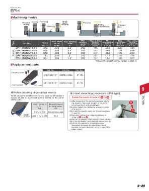
Machining modes
Shoulder Slotting Ramping Small Plunging
depth
milling plunging Drilling Enlarged
Traversing (Helical feed) hole
ap A
ae1
D1, D2 ae2
Max. depth Max. ramping Max. Max. cutting Min. Max. Max. cutting
width in
Type Cat. No. øDc (in) ap (in) angle plunging plunging machinable machinable enlarged hole
width in
Tool ø
of cut
hole ø
hole ø
depth
θ
ae2* (in)
øD2* (in)
ae1 (in)
øD1 (in)
A (in)
EPH13R012M12.0-2 .472 .472 3.5˚ .012 .118 .630 .925 .461
Straight EPH18R016M16.0-3 .630 .630 3.5˚ .012 .157 .866 1.24 .618
.630
.618
.866
1.24
3.5˚
.012
.157
.630
EPH18R016M16.0-2
1.56
2˚
.776
.630
.157
1.14
.787
.012
EPH18R020M20.0-3
1.54
.630
.012
1.95
.984
EPH18R025M25.0-4
1.5˚
.157
.972
*Where the insert corner radius ≤ .008 in
Replacement parts
Cat. No. Cat. No. Cat. No.
Clamping screw
EPH13R012** CSPB-2.2SH IP-7D
EPH18R016** CSPB-2.5SH IP-7D
(Insert pocket) TAC insert
9
dNotes on using large radius inserts d Insert mounting procedure (EPH-type)
When using the inserts which have a large corner radius in Fasten the inserts in order of A to B
excess of .039 in, additional work is needed to the corner
of the body. TAC Mills
q After loosening the clamping screws, place B
the insert in the insert pocket of the body
Insert corner R Required rework while pushing it with your finger.
r ε to body corner
(in) (in) w Lightly fasten the clamping screws in order
of A and B. A
≤
ε ≤
0 r .039 No additional work e For all the inserts, carry out the above steps
q and w.
Body r Securely tighten the clamping screws in
ε ≤
corner .039 < r .078 R2.0
order of A and B .
(Refer to the standard tightening torque values.)
t For all the inserts, carry out the above step r.
y Check the condition of insert seating,
clearance between the insert and insert
pocket, the tool diameter, and the peripheral
edge runout.
Most unmarked items are available on a RFQ basis, contact your sales rep for more information.
9–89