
Page 678 - Tungaloy Catalog
P. 678
Hybrid TAC Mills Multi-functional type with center cutting edge
EVH
Standard cutting conditions
dShoulder milling, Slotting Carbon steels and Alloy steels and Aluminum alloys Aluminum alloys
Work material alloy steels prehardened steels Stainless steels Cast irons (Si < 13%) (Si ≥ 13%)
Hardness < 30HRC 30 ~ 40HRC < 250HB - - -
Cutting speed Vc = 160 ~ 400 SFM Vc = 100 ~ 330 SFM Vc = 160 ~ 400 SFM Vc = 200 ~ 140 SFM Vc = 330 ~ 980 SFM Vc = 330 ~ 650 SFM
No. of rev. n Feed vf No. of rev. n Feed vf No. of rev. n Feed vf No. of rev. n Feed vf No. of rev. n Feed vf No. of rev. n Feed vf
Conditions min -1 in/min min -1 in/min min -1 in/min min -1 in/min min -1 in/min min -1 in/min
ap ap Tool dia. ø.394 2550 15 1910 8 2550 15 3180 20 6370 40 4770 26
(in) ø.500 2120 13 1590 6 2120 13 2650 17 5300 33 3980 22
ae ø.625 1590 9 1190 5 1590 9 1990 13 3980 25 2980 17
Side cutting Slotting Depth of Side ap < .25D ap < .25D ap < .25D ap < .25D ap < .25D ap < .25D
a p: Axial depth of cut cut cutting ae < .2D ae < .2D ae < .2D ae < .3D ae < .3D ae < .3D
a e: Radial depth of cut Slotting ap < .1D ap < .1D ap < .1D ap < .006D ap < .2D ap < .2D
dDrilling•Plunging Carbon steels and Alloy steels and Aluminum alloys Aluminum alloys
Work material Stainless steels Cast irons
alloy steels prehardened steels (Si < 13%) (Si ≥ 13%)
Hardness < 30HRC 30 ~ 40HRC < 250HB - - -
Cutting speed Vc = 160 ~ 400 SFM Vc = 100 ~ 330 SFM Vc = 160 ~ 400 SFM Vc = 200 ~ 460 SFM Vc = 330 ~ 980 SFM Vc = 330 ~ 980 SFM
No. of rev. n Feed vf No. of rev. n Feed vf No. of rev. n Feed vf No. of rev. n Feed vf No. of rev. n Feed vf No. of rev. n Feed vf
Conditions min -1 in/min min -1 in/min min -1 in/min min -1 in/min min -1 in/min min -1 in/min
ø.394 2550 5 1910 3 2550 5 3180 7 6370 18 4770 11
Tool dia. ø.500 2120 4 1590 3 2120 4 2650 6 5300 15 3980 9
(in)
ø.625 1590 3 1190 2 1590 3 1990 5 3980 11 2980 7
Note: d In slotting or pocketing where chips tend to stay in the cutting depth of cut to 1/2 to 2/3 times the values shown in the table.
zone, use an air blast to remove chips to prevent chip recutting. d Tool overhang length must be as short as possible to avoid
d When chips tend to weld excessively on the cutting edge such chatter. When the tool overhang length is long, decrease the
as in machining aluminum alloys, use a water soluble cutting number of revolutions and feed.
fluid. d Cutting conditions are generally limited by the rigidity and
d In the case of cutting a casting skin or a heavily interrupted power of the machine and the rigidity of the workpiece.
work surface, decrease the feed per tooth and the maximum When setting the conditions, start from half of the values of
the standard cutting conditions and then increase the value
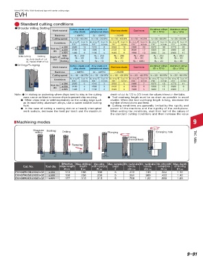
Machining modes 9
Shoulder Slotting
milling Drilling Plunging Enlarging hole
Drilling TAC Mills
(Helical feed)
Ramping
H1
H ae
ap ap W
D1, D2
Effective Max.drilling Max.cutting Max. ramping Min. machinable Min. machinable Max. cutting width Max.depth
Cat. No. Tool dia. edge length depth width in plunging angle hole dia. hole dia. in enlarging hole of boring
ap (in) H (in) W (in) θ øD1 (in) øD2 (in) ae (in) H1 (in)
EVH06R039U0050-02 ø.394 .118 .196 .196 5 .472 .749 .354 1.12
EVH07R050U0050-02 ø.500 .138 .236 .236 5 .551 .906 .433 1.42
EVH09R063U0063-02 ø.625 .177 .315 .315 5 .708 1.22 .590 1.89
Most unmarked items are available on a RFQ basis, contact your sales rep for more information.
9–91