
Page 680 - Tungaloy Catalog
P. 680
10-1 thru 10-33 421 - 465:Endmilling 8/9/11 5:12 PM Page 435
Hybrid TAC Mills Multi-functional type for high-feed milling
EXH E-Series 435
Standard cutting conditions
General Cutting Conditions
Face Slotting Work Material Carbon Steels and Aloy Alloy Steels and Stainless Steels Cast Irons Aluminum Alloys Aluminum Alloys
Steels Prehardened Steels (Si<12%) (Si>13%)
Milling Hardness <30HRC 30~40HRC <250HB - - -
Cutting Speed vc=330~1,000 SFM vc=330~820 SFM vc=330~1,000 SFM vc=330~1,000 SFM vc=330~1,650 SFM vc=330~1,000 SFM
Conditions RPM Feed (ipm) RPM Feed (ipm) RPM Feed (ipm) RPM Feed (ipm) RPM Feed (ipm) RPM Feed (ipm)
0.394 4770 56 3820 30 4770 56 6360 100 9550 226 6360 125
Tool dia.
0.500 3980 47 3180 25 3980 47 5300 83 7950 188 5300 104
ap ap (in)
0.625 2980 35 2380 19 2980 35 3970 62 5960 141 3970 78
0.394 ap<0.024 ap<0.020 ap<0.024 ap<0.024 ap<0.024 ap<0.024
Depth of
ap: Axial depth of cut cut (in) 0.500 ap<0.024 ap<0.020 ap<0.024 ap<0.024 ap<0.024 ap<0.024
0.625 ap<0.031 ap<0.024 ap<0.031 ap<0.031 ap<0.031 ap<0.031
Carbon Steels and Aloy Alloy Steels and Aluminum Alloys Aluminum Alloys
Plunging Work Material Steels Prehardened Steels Stainless Steels Cast Irons (Si<12%) (Si>13%)
Hardness <30HRC 30~40HRC <250HB - - -
Cutting Speed vc=330~1,000 SFM vc=330~820 SFM vc=330~1,000 SFM vc=330~1,000 SFM vc=330~1,650 SFM vc=330~1,000 SFM
Conditions RPM Feed (ipm) RPM Feed (ipm) RPM Feed (ipm) RPM Feed (ipm) RPM Feed (ipm) RPM Feed (ipm)
0.394 4770 9 3820 6 4770 9 6360 17 9550 30 6360 17
Tool dia.
0.500 3980 8 3180 5 3980 8 5300 15 7950 25 5300 15
(in)
0.625 2980 6 2380 4 2980 6 3970 11 5960 19 3970 11
ap: Axial depth of cut ae: Radial depth of cut
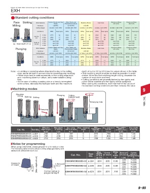
Machining Modes
Note: • In slotting or pocketing where chips tend to stay in the cutting depth of cut to 1/2 to 2/3 times the values shown in the table.
zone, use an air blast to remove chips for preventing chip recutting. When using CAD/CAM, please program it as for radius cutter. The
• Tool overhang length must be as short as possible to avoid
chatter. When the tool overhang length is long, decrease the
• When chips tend to weld excessively on the cutting edge such following table shows actual cutting edge geometry and amount of
Face
Plunging
milling
Enlarging hole
Sloting
number of revolutions and feed.
as in machining aluminium alloys, use a water soluble cutting unfinished work cut.
Drilling
fluid. Drilling • Cutting conditions are generally limited by the rigidity and
ap (Max. depth of
(Helical feed)
• In the case of cutting a casting skin or a heavily interrupted power of the machine and the rigidity of the workpiece.
Ramping
work surface, decrease the feed per tooth and the maximum When setting the conditions, start from half of the values of
cut)
Amount
H1 the standard cutting conditions and then increase the value Endmills
of uncut
H
Machining modes W D1, D2 ae
ap
ap
W Corner radius in programming 9
M
Shoulder Tool Dia. Effective Max. Depth Max. cutting Max. ramping Min. machinable Max. machinable Max. cutting width Max. depth of
Plunging
Drilling
Cat No.
milling Slotting Drilling (in.) edge length of drilling width in plunging angle hole dia. hole dia. in enlarging hole boring
(Helical feed)
(D2)
(θ°)
(W)
(ae)
(D1)
(Ap)
(H1)
(H)
EXH06R010M10.0-02 Ø 0.6 5 5 5 12 19 7 30
Enlarging hole TAC Mills
EXH07R012M12.0-02 Ø 0.6 6 6 5 14 23 9 36
EXH09R016M16.0-02 Ø 0.6 8 8 5 18 31 12.5 48
Ramping
Tool Dia. Max. Depth of Cut Corner R of Insert Amount of Uncut Corner Radius in
Cat No. (W)
(in.) (ap) (re) (t) Programming
H1
0.0276 R0.02
EXH06R039U0050-02 H 0.394 0.024 0.020 ae 0.098 0.0236 R0.04
ap W 0.0276 R0.02
ap
EXH07R050U0050-02 0.500 0.024 0.020 0.098
D1, D2 0.0236 R0.04
0.0315 R0.02
EXH09R063U0063-02 0.625 0.031 0.031 0.118 0.0276 R0.04
R0.06
Effective Max.depth Max. cutting Max. ramping Min. 0.0236 Max. cutting Max.depth
Max. machinable
width in
Cat. No. Tool dia. edge length of drilling width in plunging angle machinable hole dia. enlarging hole of boring
hole dia.
Notes ap (in) H (in) W (in) θ D1 (in) D2 (in) ae (in) H1 (in)
In slotting or pocketing where chips tend to stay in the cutting zone, use an air blast to remove chips to prevent chip recutting.
5
.748
EXH06R039U0050-02 ø.394 .236 cutting edge such as when machining aluminum alloys, use a water soluble cutting fluid. .276 1.25
.197
.472
.197
When chips tend to weld excessively on the
.906
.354
.551
.236
.236
.236
5
EXH07R050U0050-02 ø.500 skin or a heavily interrupted work surface, decrease the feed per tooth and the maximum depth of cut to 1/2 to 2/3 times the values 1.42
In the case of cutting a casting
EXH09R063U0063-02 ø.625 .315 .315 .315 5 .709 1.22 .492 1.89
shown in the table.
Tool overhang length must be as short as possible to avoid chatter. When the tool overhang length is long, decrease the number of revolutions and feed.
Cutting conditions are generally limited by the rigidity and power of the machine and the rigidity of the workpiece. When setting the conditions, start from half of the
Notes for programming
values of the general cutting conditions and then increase the value gradually while making sure the machine is running normally.
When using CAD/CAM, please program it a for radius cutter.
The following table shows actual cutting edge geometry and
amount of unfinished work cut. Max. Corner Wide Amount Corner
of
radius in
Cat. No.
of uncut
Customer Service: 1-888-554-8394 Tool depth of insert : Stocked Standard programming
tooth
of cut
dia.
t (in)
ap (in)
R
W
Technical Support: 1-888-554-8391
rε
: Non-Stocked Standard
.024
R.039
Corner rε t: Amount EXH06R039U0050-02 ø.394 .024 .020 0.98 .028 R.020
of insert 20˚ (Max. depth of cut) uncut EXH07R050U0050-02 ø.500 .024 .020 0.98 .028 R.020
R.039
.024
W ap Corner radius in EXH09R063U0063-02 ø.625 .031 .031 .118 .031 R.020
R.039
.028
programming R
R.060
.024
Most unmarked items are available on a RFQ basis, contact your sales rep for more information.
9–93