
Page 703 - Tungaloy Catalog
P. 703
TAC Flash radius mills
TRD12 16, ERD12
•
Standard cutting conditions
Work materials Grades Cutting speed Feed per tooth f (in/t)
Vc (SFM) T/ERD12 T/ERD16
AH120 390 ~ 720 .012 ~ .020 .012 ~ .024
Carbon steels (1018,1055) AH330 460 ~ 790
< 300 HB .008 ~ .016 .008 ~ .020
UX30 260 ~ 390
AH120 330 ~ 660 .008 ~ .018 .008 ~ .020
Alloy steels (4140, 4340) AH330 390 ~ 720
< 300 HB .006 ~ .014 .006 ~ .016
UX30 200 ~ 390
Die steels (H13,P20 etc.) AH120 260 ~ 590 .008 ~ .014 .010 ~ .018
< 300 HB AH330 330 ~ 660 .004 ~ .012 .004 ~ .016
Stainless steels (JIS SUS304 etc.) AH130•AH140 330 ~ 660 .008 ~ .012 .008 ~ .016
Grey Cast irons AH120 390 ~ 790 .012 ~ .020 .012 ~ .024
(JIS CLASS 25-40) AH330 490 ~ 820 .008 ~ .016 .008 ~ .020
Hard materials < A980 AH120 200 ~ 460 .003 ~ .010 .004 ~ .012
Note: When the depth of cut is smaller than .078 in, use the higher limit of feed values shown
above. When larger than .118 in, use the lower limit of the feed values.
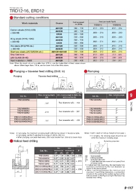
Plunging + traverse feed milling (Unit: in) Ramping
Plunging Traverse feed milling L L
Feed Feed Feed
ap ap
θ
Unit: in
Max. plunging depth Min. traverse length to flatten the Max. ramping angle 9
Cat. No. Cat. No.
(ap) bottom surface (L) θ
TRD12050RU TRD12050RU 8º
Tool diameter øD1 - .433
.157
TRD16080RU TRD16080RU 4º TAC Mills
TRD16100RU Tool diameter øD1 - .591 TRD16100RU 3º
TRD16125RU .216 TRD16125RU 2º
ERD12125RSU/RLU ERD12125RSU/RLU 16º
ERD12150RSU/RLU Tool diameter øD1 - .433 ERD12150RSU/RLU 8º
ERD12200RSU/RLU .157 ERD12200RSU/RLU 6º
Notes: • In plunging, the maximum plunging depth is limited as shown in the above table. Notes: • tanθ = depth of cut: ap / length of tool pass: L
• In plunging, set the Z-axis feed in a range of .002 to .004 in/t. • In ramping, the ramping angle should be set
• When plunging, use peck-feed every .039 in (or smaller than .039 in) to break chips. within the maximum ramping angle.
Helical feed drilling Remaining projection
øD
P
øD2 Unit: in
Min. Max.
P
Cat. No. machining dia. machining dia P
øD øD 2 øD øD 2
TRD1205RU 3.47 1.50 3.86 1.89 < .236 øD1 : Tool diameter
TRD16080RU 5.67 2.52 6.22 3.07 øD : Drilling diameter
øD2 : Tool pass diameter
TRD16100RU 7.24 3.31 7.80 3.85 < .315 P : Z-axis feed per one round of tool pass (Pitch
of helical cycle)
TRD16125RU 9.21 4.29 9.76 4.84 • In helical feed hole machining, the machinable hole
ERD12125RSU/RLU 2.05 .750 2.44 1.25 diameters are limited by the tool diameter as
shown in the above tables.
ERD12125RSU/RLU 2.68 1.10 3.07 1.50 < .236 • When machining between the minimum and
øD1 ERD12200RSU/RLU 3.47 1.50 3.86 1.89 maximum machining diameters, a projection
remains in the center of the bottom surface of the
øD hole as shown in the Figure at right. Remove it by
traverse feed milling.
Most unmarked items are available on a RFQ basis, contact your sales rep for more information.
9–117