
 714.897.1700
 Chat
Chat
 Email
Email
 Quotes
 Quick Order
Product Information
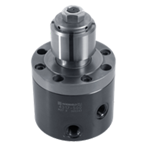
700 to 5000 psi max (depending on bore size)Double Acting Self-Centering Bore Clamps provide locating, internal clamping, and supporting in one unit, exerting force both radially and downward against a hardened support surface. This compact design uses an expanding Segmented Clamping Bushing to exert high clamping force with self-centring repeatability within .0002". These bore clamps are particularly suitable for clamping workpieces with machined bored holes and a support surface square to the hole axis. Available in three types: Self-centring Self-centring in one axis, with .020" float in the other axis Without centring, with .020" float in all directions. Bore clamps are available in one housing diameter with five different cone sizes to cover five internal-diameter clamping ranges: 15.9 to 21.9mm 22 to 27.9mm 28 to 33.9mm 34 to 39.9mm 40 to 46mmSegmented Clamping Bushings must be ordered separately and are available in 0.1mm increments. After mounting, the clamping bushing is concentric to the housing's bottom locating post within .003". Clamping repeatability is within .0002".
Application Information
These Bore Clamps exert force both radially and downward against a hardened support surface. Dual Mounting Capability Standard Fittings or Manifold Mounting.
Clamping Action
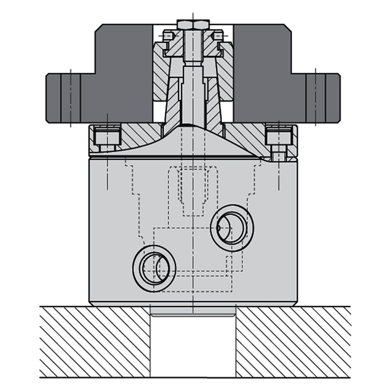
Self-Centering Bore Clamps are a combination of a double-acting pull-type cylinder and a segmented bushing which is pulled by a drawbar over a fixed cone. This causes the segmented bushing to expand radially to the bore diameter of the workpiece. The simultaneous axial movement forces the workpiece downward onto the hardened support surface of the housing. Downward clamping force is proportional to operating pressure and will vary somewhat depending on the friction coefficient within the bore.
Design Considerations
See Dimensions page for allowable bore tolerances and required contact length. Do not exceed the maximum operating pressure listed for the bore-diameter range or this will damage the drawbar. Avoid repeated clamping without the workpiece in place because this strains the vulcanized segment joints. Maximum operating temperature for the segmented bushing is 175 Degree.
Mounting & Fluid Supply
Mounting the Clamp: Bore a locating hole in the fixture plate for the housing's bottom locating post. Fasten with four socket-head cap screws. Mounting & Adjustment of the Segmented Bushing: With the Bore Clamp unclamped and the drawbar's lock nut removed, screw the end plug of the Segmented Clamping Bushing onto the drawbar. Check the bushing's diameter with a calliper and continue turning until the diameter is .004 to .008" less than the clamping diameter, to allow easy loading of the workpiece. Secure with the lock nut. Fluid Supply: Two 1/4" BSPP ports, A for clamping, B for unclamping. For optional manifold mounting, use the A and B manifold ports underneath the clamp by unscrewing the sealing plugs and installing two CLR-3000-343-SW O-rings (also install two CLR-810-F Port Plugs in the 1/4" BSPP ports). Do not use NPT fittings. These clamps also have a 1/8" BSPP port marked M for air connection when using the pneumatic seat check.
Material
| ITEM | MATERIAL | HEAT TREAT | FINISH |
| Body | Steel | - | - |
| Piston and workpiece support | Steel | Case Hardened | - |
| Segmented Clamping Bushing | Steel | Case Hardened, with Vulcanized segment joints | - |
Parts Specification
| Part Number | NOMINAL DIAMETER | ALLOWABLE WORPIECE TOLERANCE |
| CLR-3338-255 | 1.0039 (25.5mm) | 1.0000 to 1.0236 |
Warning:
This product can expose you to materials and/or chemicals including arsenic, lead, and other materials and/or chemicals which are known to the state of California to cause cancer and/or reproductive harm.
For more information, visit www.P65Warnings.ca.gov
